Raspberry Pi GPIO
pi-top’s hardware expansion capabilities are based on the Raspberry Pi’s 40 General Purpose Input Output (GPIO) pins. These offer a way to interface with external components, such as lights and motors.
These GPIO pins can be configured to work in different modes; they can work as an input (so that the Raspberry Pi can read a digital signal), as an output (in order to generate a signal to control a component), as a PWM generator, or as part of a set of pins in order to communicate using several protocols such as I2C, SPI and UART.
Related link: ![]() Raspberry Pi GPIO Pinout
Raspberry Pi GPIO Pinout
pi-top Plates
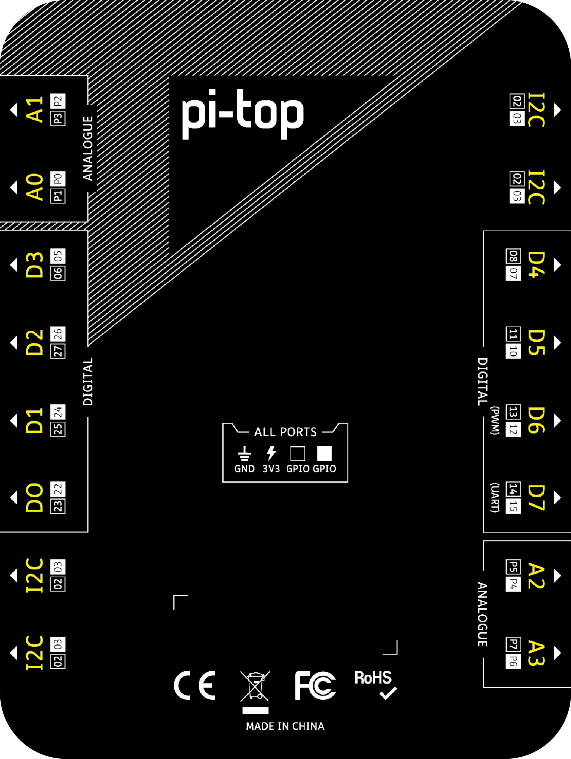
As well as exposing the Raspberry Pi GPIO pins directly on the front, the pi-top 4 uses plates to add additional hardware functionality and organise the GPIO’s into ports which are easier to use.
Foundation Plate
-
8 Digital Ports (labelled D0 -> D7)
-
4 Analog Ports (labelled A0 -> A3)
-
4 I2C Ports (labelled I2C)
Expansion Plate
-
8 Digital Ports (labeled D0 -> D7)
-
4 Analog Ports (labeled A0 -> A3)
-
4 I2C Ports (labeled I2C)
-
4 Encoder Motor Ports (labeled M0 -> M3)
-
4 Servo Motor Ports (labeled S0 -> S3)
Both plates have an internal MCU that is in charge of handling Analog measurements and in the case of the Expansion Plate, communicating with Motors and Servos.
Analog, Encoder Motor and Servo Motor Ports are controlled by the internal microcontroller each Plate has and they’re not connected to the Raspberry Pi directly.
Digital Ports are wired directly to the Raspberry Pi GPIO as described by the following table.
|
Plate Port |
Raspberry Pi GPIO Ports |
|
|
D0 |
22 | 23 |
| D1 | 24 | 25 |
| D2 | 26 | 27 |
|
D3 |
5 | 6 |
| D4 | 7 | 8 |
| D5 | 10 | 11 |
| D6 | 12 | 13 |
| D7 | 15 | 16 |
|
I2C |
2 | 3 |
Analog Sensor Measurement Variation
Analog sensor measurements are read by the pi-top using an analog to digital converter (ADC). These measurements can present a variation of around 1% for the same input and are related to the nature of analog signals, which are continuous (as opposed to digital signals, which are discrete).
pi-top[4] GPIO Usage
The pi-top[4] has 2 components that require constant communication with the Raspberry Pi for the device to work properly: the Miniscreen and the Hub.
Miniscreen Communication
The Raspberry Pi communicates with the Miniscreen through an SPI bus. The Raspberry Pi 4 has 2 available SPI buses and each bus uses 5 or 6 GPIO pins.
The default is for the pi-top 4 to use SPI bus 1. The bus used for communicating with the Miniscreen is configurable through a CLI.
The Miniscreen will require to use GPIO pins 7→11 if using SPI bus 0 or pins 16→21 if using SPI bus 1.
Hub Communication
The communication with the Hub is through I2C, using GPIO pins 2 and 3. The Expansion & Foundation Plate I2C ports are directly wired to these pins. Multiple devices can be wired to the same I2C bus and work simultaneously.
Limitations
Port Collisions
Given the limited number of GPIO ports, there can be cases where multiple pi-top components are wired to use the same GPIO but expect it to be configured in a different mode. These port collisions will cause unexpected behaviours in these components.
| GPIO Pins | Miniscreen SPI Bus | Plate Port |
| 7, 8 |
SPI Bus 0 |
D4 |
| 10, 11 |
SPI Bus 0 |
D5 |
If a component is connected to a port that’s already in use by the Miniscreen, it will not be controllable through the python libraries. Also, if the attached component can produce an output, you might notice that its state can vary.
For example, connecting an LED to port D4 if the screen is configured to use SPI bus 0 will cause it to be turned on or to flicker. This is because it’s receiving the electrical signals from the SPI bus as an input.
Workaround
The SPI bus used by the Miniscreen can be configured using a CLI with the command:
pi-top oled spi <BUS NUMBER>
Where <BUS NUMBER> is either 0 or 1.
Once this command is run, the GPIO ports of the new SPI bus will be reconfigured and will free up the pins from the old SPI bus, making them available for users to connect to any component.
Unknown State on Boot
When the Raspberry Pi boots, it configures all its GPIO ports as inputs. Later in the boot process, the GPIO ports will be configured to a secondary function by the kernel or an application. For example, if I2C or SPI buses are in use, the associated pins will be configured accordingly.
In the case where a pin isn’t configured on boot, it will remain as an input. This means that connecting an output device to it will cause it to work erratically until you configure and use that port as an output.
For example, if you connect an LED to the digital port D3 on boot, you might notice that it’s lit or in a dimmed state.
Workaround
If you do have an issue with the default state of ports before they are in use, it’s possible to configure them as an output on boot by modifying the /boot/config.txt file using the gpio command as follows:
gpio=<GPIO NUMBER>=op,dl
That line will configure <GPIO NUMBER> as output (because of the op parameter) and set it to a low/off state (because of the dl or drive-low parameter)
For example, to configure port D4 as an output and set it to a “low” state you need to know the GPIO pin where it’s connected. By looking up the D4 port in the first table of this document, we can determine that it’s connected to GPIO pin 7. This way, the line to add to /boot/config.txt is:
gpio=7=op,dl
Interaction with other Raspberry Pi Hardware
Sense Hat
Related Link: ![]() Sense HAT at Raspberry Pi GPIO Pinout
Sense HAT at Raspberry Pi GPIO Pinout
The Sense Hat includes a RGB LED Matrix, Joystick, Gyroscope, Accelerometer, Magnetometer, Temperature, Pressure and Humidity sensors. All of these operate over a I2C bus using the following addresses:
| Component | I2C Address |
|
LED Matrix & Joystick |
0x46 |
|
IMU (Accelerometer & Magnetometer) |
0x1c - 0x1e, 0x6a - 0x6b |
|
Pressure & Temperature Sensor |
0x5c |
|
Humidity & Temperature Sensor |
0x5f |
The pins used to communicate with the SenseHat are GPIO 2 & 3.
The SenseHat has an internal microcontroller in charge of manipulating the LED Matrix and the Joystick. GPIO pins 23 & 24 can be used to send interruptions to it and GPIO 8 & 25 can be used to flash its EEPROM. Regular users should never need to use these pins.
Compatibility
The SenseHat is compatible with the pi-top[4]. Follow these instructions to connect the HAT to the pi-top:
-
Before attaching the Sense Hat to your pi-top[4], ensure that it’s shut down.
-
Push the Sense Hat carefully onto the pins of your pi-top[4] GPIO header.
-
Turn on your pi-top[4].
You should see the RGB LED Matrix turn on and display a rainbow for a few seconds, then it should turn off. If it doesn’t turn off it’s a sign that there might be a connection issue, so repeat the previous steps.
Some guides on the internet suggest editing the /boot/config.txt file and adding the line dtoverlay=rpi-sense in cases where the hat is not detected. This forces the Sense Hat overlay to load on boot to allow the Pi to recognize the device.
Limitations
I2C bus issues on reboot
Rebooting the pi-top[4] with a Sense Hat attached causes issues with the I2C bus; this causes the miniscreen not to work properly and the Sense Hat not to be detected.
Workaround
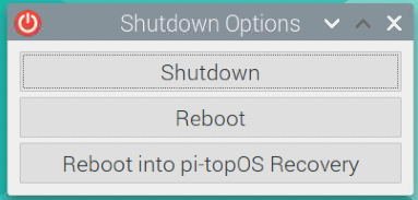
It’s recommended to do a full power cycle if you need to reboot your pi-top while the Sense Hat is attached. This means to use the ‘Shutdown’ option if you’re using the desktop or to run sudo shutdown -h now if using a terminal; and then manually power the device back on using the power switch of the pi-top.
Sound Sensor measurements on a Foundation Plate
The SenseHat has an impact on Sound Sensor measurements made on a Foundation Plate. When a Sense Hat is connected to a pi-top, the perceived loudness by the sensor decreases. This doesn't happen with other analog components such as the Light Sensor or the Potentiometer.
The Sense Hat doesn't affect the measurements if the components are connected to an Expansion Plate.