pi-top Maker Architecture (PMA) Connector
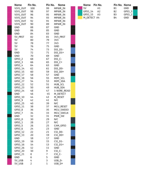
The PMA Connector has many exciting things coming through it. Firstly it has all the Raspberry Pis GPIOs from the 40pin connector, as well as the Camera and Display Serial Interfaces. It also has all the power rails you may need for your individual projects. You can find the full list of specifications and details about all the pins and connector at the bottom of the page.
It’s a 100 pin connector (50x2) with a 0.80 mm pitch. The manufacturer is Amphenol and the recpt part number is 10144517-10XXXXXX while the plug part number is 10144518-10XXXXXX. The Plug is mounted inside the pi-top [4] but all our plates use the receptacle.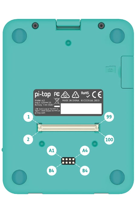
| Power Pins | ||||
|---|---|---|---|---|
| Name | Function | Voltage (Volts) | Max Current (Amps) | Descriptions |
| VSYS_OUT | Power Out | 6.4 - 8, 12, 15 | 3 | Outputs System Voltage. If using Battery power then 6.4 - 8.4Volts. If using USB-C Power 12 or 15 Volts. Max output is 3A. Fuse protected |
| MPWR_IN | Power In | 9 - 14 | 3 | Input to System Voltage. Lower priority to USB-C PSU. Higher priority to battery power. Can be used to charge battery pack. Fuse Protected |
| 5V_USB | Power Out | 5 | 0.6 | Direct from Raspberry Pi USB Port |
| 5V_PRST | Power Out | 5 | 0.75 | Available when device is powered off. Turns off when battery power dips below 5%. Fuse protected |
| 5V | Power Out | 5 | 3.5 | Shares same source as 5V from 40pin connector and pogo pins but separate to 5V supplied to Raspberry Pi. Fuse protected |
| 3V3_PRST | Power Out | 3.3 | 0.15 | Available when device is powered off. Turns off when battery power dips below 5%. Fuse Protected |
| 3V3 | Power Out | 3.3 | 1.5 | Shares same source as 3V3 from 40pin connector. Fuse protected |
| Data Pins | ||
|---|---|---|
| Name | Function | Description |
| GPIO_XX | I/O | GPIOs tied directly to Raspberry Pi. ESD Protected. Direct connection between the 40pin connector and the PMA Connector |
| MCU_RESET | Input | External Reset to pi-topHub MCU. (Connect to GND to reset) |
| MCU_SWDIO | I/O | MCU Serial Wire Data Input/Output |
| MCU_SWCLK | I/O | MCU Serial Data Clock |
| PWR_SW | Input | Tied to device power switch. High to turn on. Logic High @ 2.2V |
| USB_DX | Data | USB data pair from USB-Hub Controller on pi-top Hub |
| DSI_XX | Data | Display Serial Interface from Raspberry Pi |
| CSI_XX | Data | Camera Serial Interface from Raspberry Pi |
| MIPI_SXX | I2C |
MIPI I2C from Camera/Display Serial Interface from Raspberry Pi |
| Pogo Pins | ||
| Name | Function | Description |
| A1 | Power Out | 5V Power Out. Shares same source as 5V from 40pin connector and PMA connector (modular connector). Separate to the 5V supplied to the Raspberry Pi. Fuse protected |
| A2 | I/O | GPIO14. Connected directly to Raspberry Pi. Intended to be used as UART TX though can also be used as Digital I/O |
| A3 | I/O | GPIO15. Connected directly to Raspberry Pi. Intended to be used as UART RX though can also be used as Digital I/O |
| A4 | Data | M_Detect. Used as Modular Plate Detect. Connected to pin 45 on the PMA Connector (Modular Connector). Uses an ADC to identify which plate has been docked. |
| B1/B4 | GND | Ground |
| B2 | Data | GPIO3. Raspberry Pi I2C SCL (Clock). Do not use as Digital I/O |
| B3 | Data | GPIO2. Raspberry Pi I2C SDA (Data). Do not use as Digital I/O |